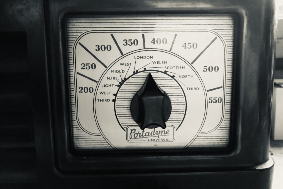
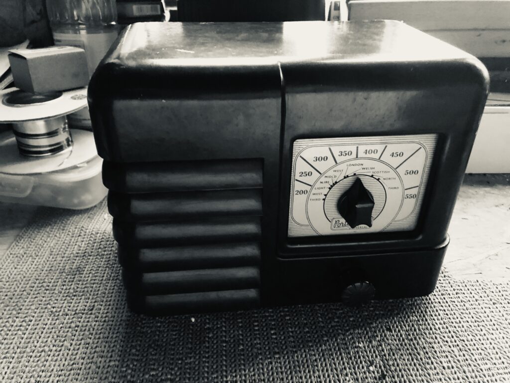
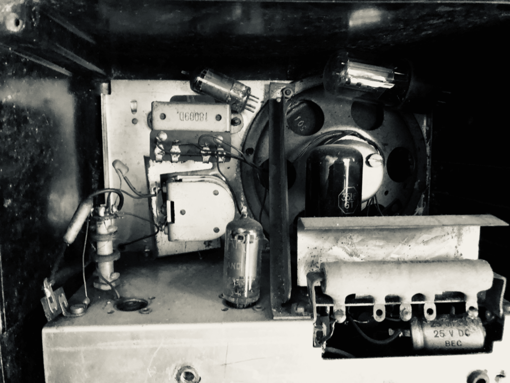
Walking around an antique shop in Crewkerne, I came across an old valve radio – a Portadyne Unversal – from 1953. Peering in through the back cover I could see that a couple of the valves were free-range within the case, one of which was wedged up at top, next to the speaker.
After negotiating a more sensible price for the radio (and saving it from being “ripped apart to fit an Alexa inside it“, it came home with me.
There’s something about switching on a vintage radio and waiting for the valves to warm up, the glow of the heaters and then listening as the sound comes up and the radio comes to life. So, in these few articles, I wanted to discuss the Portadyne Universal TRF receiver and how it works.
It’s a fairly basic radio, consisting of four valves (and that includes the power supply rectifier). The set is powered by a 240V a.c. feed. If you are going to work on the vintage valve sets, please take appropriate precautions as the chassis can be live even when the set is switched off.
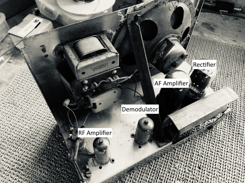
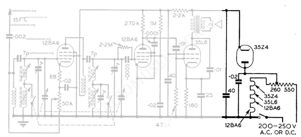
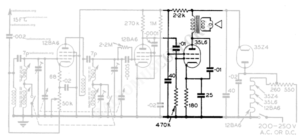
The circuit diagram is shown below and was downoaded from radiomuseum.org. It consists of:
- an RF amplifier
- a demodulator
- an audio amplifier
- the power rectifier
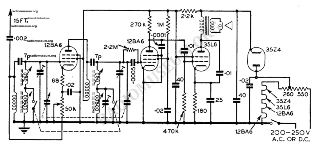
Using this diagram, we can work through the circuit. Initially we’ll start with the rectifier, before moving on to follow the signal from antenna to speaker. It’s worth noting that the physical layout of the valves follows the layout shown in the circuit diagram.
The Power Supply
We start this article by having a quick look at the power supply in the 1953 Portadyne Universal radio, that I’ve managed to get up and running with minimal effort. It’s a simple design with its three stages plus the power supply… and that’s where we’re going to start off.
Before going any further, if you’re tempted to get an old valve radio up and running again, please be careful. The chassis can be live, even though you’ve switched the radio off on the front panel. Also, try not to be tempted to just plug the radio in, “just to see if it works”. It’s tempting… really tempting, but a component fault can do some major damage to other [expensive / hard-to-find] components. Take the time to complete some basic tests and then power it up slowly.
Rectification
This radio uses a very simple power supply circuit, which can be fed with either 240v A.C. or D.C. In practice, you’ll likely plug it into the mains and so you’ll be providing the radio with 240V A.C. Note how the mains on/off switch is wired in. The single pole switch is wired into the neutral side – which was a very common thing to do.
The problem is that the live side of the wiring can make the chassis live via the voltage dropper resistor and the series heaters. Touching the chassis and an earth connection make give you a little surprise…
The four valves used in this circuit all use indirectly heated cathodes, and the heaters for these valves are connected in series; again, very common procedure. However, it does mean that if one heater fails, the entire radio stops working as none of the valves can work.
The set uses two 12BA6 valves (these have a 12v heater, as denoted by the first two digits in the model number), one 35L6 (35v heater) and the 35Z4 (also a 35v heater). This last valve is important to us in the context of this article as the 35Z4 is a half-wave rectifier.
With the 240v A.C. connected, during the positive half of the cycle, the anode of the 35Z4 will be positive (with respect to the cathode). This allows electrons to flow from cathode to anode and current is passed through the valve.
However, during the negative half of the cycle, the anode will be negative with respect to the cathode. Essentially, the valve is turned off during this period and no current will flow.
This half-wave rectification is somewhat ‘lumpy’ and needs to be smoothed out to create a better D.C. supply. The 40uF capacitor performs that function. During the positive half cycle, this capacitor is charged up and as the voltage peaks, then falls back towards zero, the capacitor starts to discharge. The capacitor continues to discharge slowly, until the next positive half-cycle, when the capacitor can be charged back up again.
Things To Watch Out For
- The electrolytic smoothing capacitor failing and becoming short circuit.
- The 0.02uF capacitor failing and going short circuit, which will allow the voltage dropper to pass too big a current (depending on the fuse in the plug). Result… voltage dropper failing.
- One heater in a valve failing, which will result in none of the valves working.
- Chassis can be live when unit is apparently switched off on the front panel.
The RF Amplifier
In this article we’ll look at the RF amplifier stage of this TRF radio. This radio has one RF stage, and a detector stage followed by an AF amplifier. This would also have been known as a 1-V-1 radio, where the V is the detector stage, the number 1 before the V denotes the number of valve RF amplifier stages; the 1 after the V shows the number of valve AF stages.
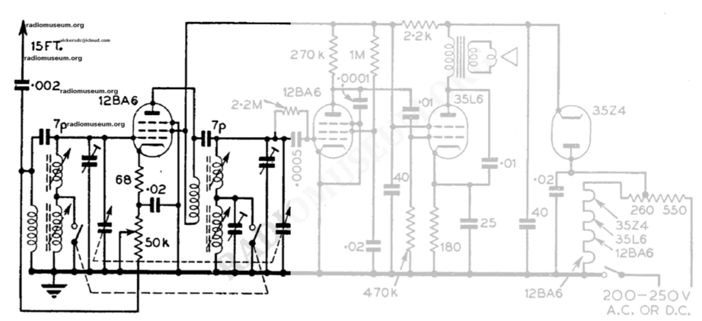
The antenna (15′ of wire) is coupled into the the antenna coil via a 2nF capacitor. The first set of coils provides MW and LW coverage, the tuned circuit created by one gang of the dual-gang variable capacitor. The LW coil is essentially shorted out when not needed. Note the trimmer capacitor across the coils too, this is to deal with stray capacitance.
The 12BA6 is a variable μ valve used to amplify the received signal. The gain of the stage is controlled by adjusting the cathode bias via the 50KΩ variable resistor, this acts as the ‘volume’ control for the radio. Across this variable resistor is a 20nF capacitor which appears as a low impedance to RF frequencies – thereby preventing RF signals from altering the bias.
Positive voltage to the anode is supplied via a second coil winding, which allows DC voltage to be applied. The amplified RF signal is also applied to this coil and then coupled into the second tuned circuit. Both tuned circuits (the antenna one and this one in the output) are tuned to the same frequency.
Demodulation
In this part, we’ll look at how the demodulator for this radio works. The radio is only capable of demodulating AM signals.
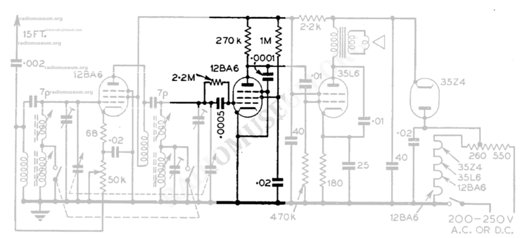
The Portadyne Universal uses the Grid Leak Detector method of demodulating the signal. The grid leak detector is formed by the 2.2MΩ resistor and 500pF capacitor connected to the control grid of the 12BA6 valve. The only source of grid bias is via the 2.2MΩ resistor.
The 100pF capacitor that is connected to the anode is there to filter out variations in plate (anode) current caused by the carrier frequency. The suppressor grid is connected directly to the cathode (which is normal) and prevents any secondary emission from the anode; because the suppressor grid is negative compared to the anode, any electrons forced from the plate, due to secondary emission, are repelled back to the plate.
The screen grid has a fixed voltage applied to it. This is designed to reduce the internal capacitance between the anode and the control grid.
The AF Amplifier
Coming soon…