The diode ring double balanced mixer is a simple device which can be used in receivers and transmitters. In this article, we’ll be testing a homebuilt mixer for a 20m transmitter.
The mixer consists of four Schottky diodes – I used BAT28 diodes – and two coils wound on toroids. The coils need to be trifilar wound and I used 10 turns of 22AWG on T50-2 cores.
This mixer has the advantage that we can set it to provide AM transmission or DSB-SC (double sideband suppressed carrier) by biasing the diodes as needed.
Equipment Needed
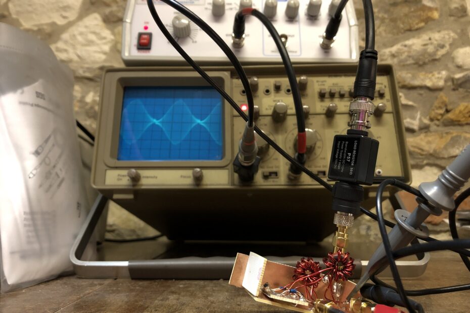
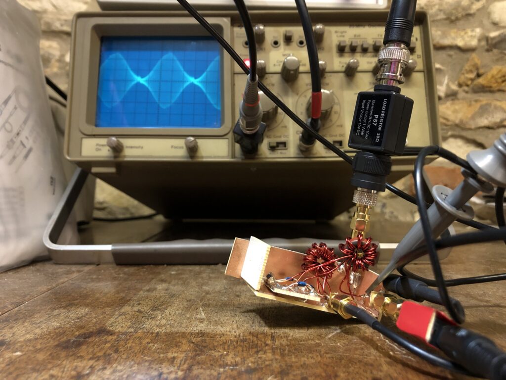
To carry out this test, I used my old school Gould OS300 oscilloscope, Pintek FG30 signal generator and a NanoVNA. The scope was fitted with a 50Ω through termination, and a second one was used on the IF port, which was fed by the signal generator. I also used my Sony ICF radio to listen to the signal output from the mixer, which was a useful confirmation that everything was working.
My signal generator was set to provide a 1kHz sine wave, which was fed to the IF port on the mixer. The Pintek FG30 also allows me to apply a DC offset to the signal, which is perfect for applying a bias to the diodes to change the signal output from the mixer.
The NanoVNA was being used as an RF signal source at 14,100kHz, which was then modulated by the signal from the function generator.
Double Sideband
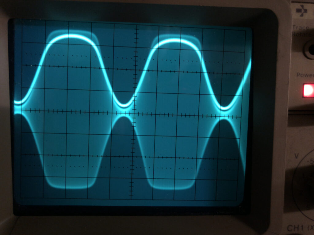
With no bias applied and the amplitude set appropriately, it’s easy to see the mixer output a DSB signal.
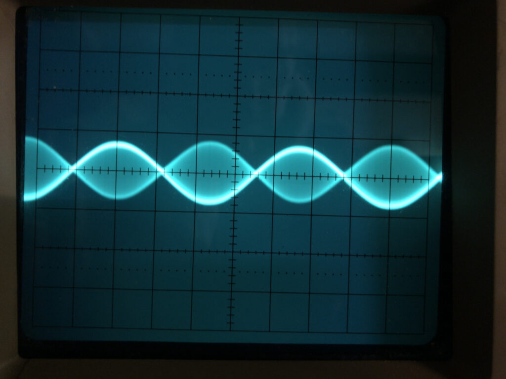
The slightly brighter line seen in the image above is the 1kHz signal fed into the mixer. You can see that the phase changes and although it could be mistaken for an AM signal at twice the modulated signal, it is DSB. This could be confirmed by using a spectrum analyser… but I don’t have one!
By contrast, let’s look at the amplitude modulated signal.
Amplitude Modulation
By providing a bias, either negative or positive, to the diodes, we can achieve AM modulation.
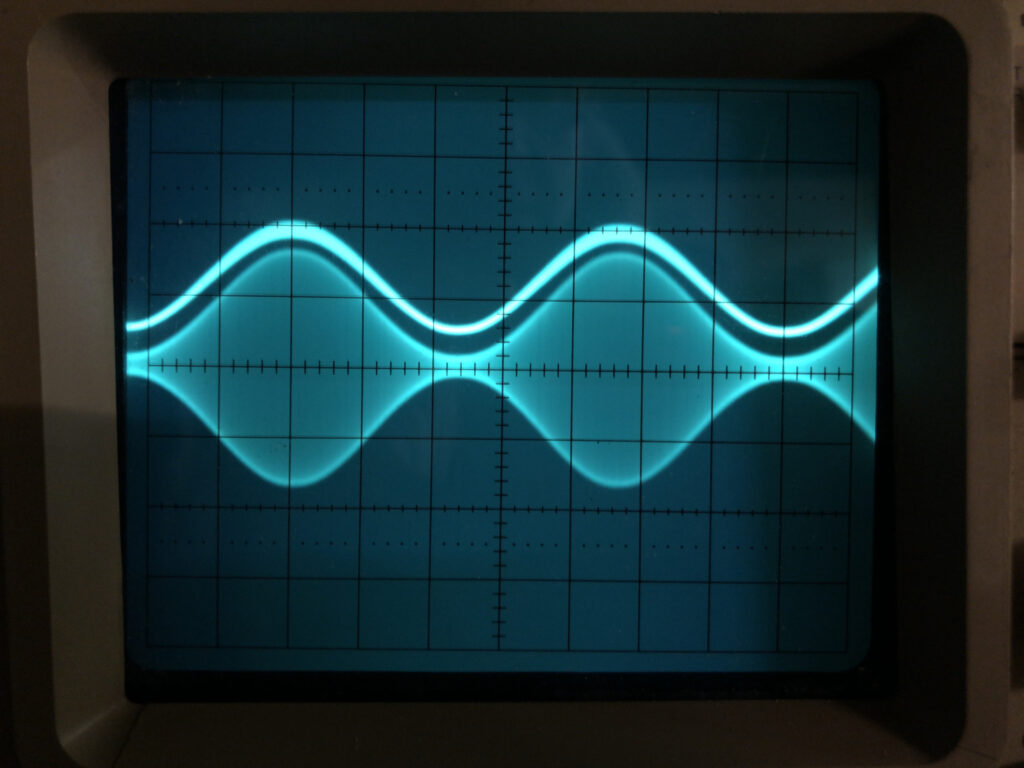
With a little careful adjustment, it’s quite easy to achieve a 100% modulated AM signal – as shown in the oscilloscope trace above. However, it can also be easy to overdrive the mixer, resulted in a distorted AM signal such as that shown below.
Summary
The diode ring double balanced mixer is simple and cheap to create. Ideally it should use a set of four matched diodes; I did a quick check on my meter and the four that I had were close, but not quite perfectly matched. The mixer was just built on copper clad board, with a smaller piece cut for the diode ring, with the copper cut into four sections.
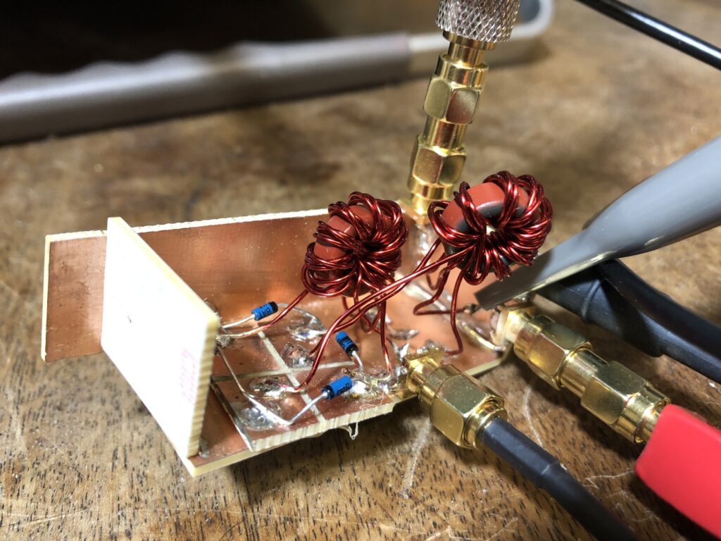
I’m not sure that the build is going to win any awards, but as something just to experiment with, it worked fine.